

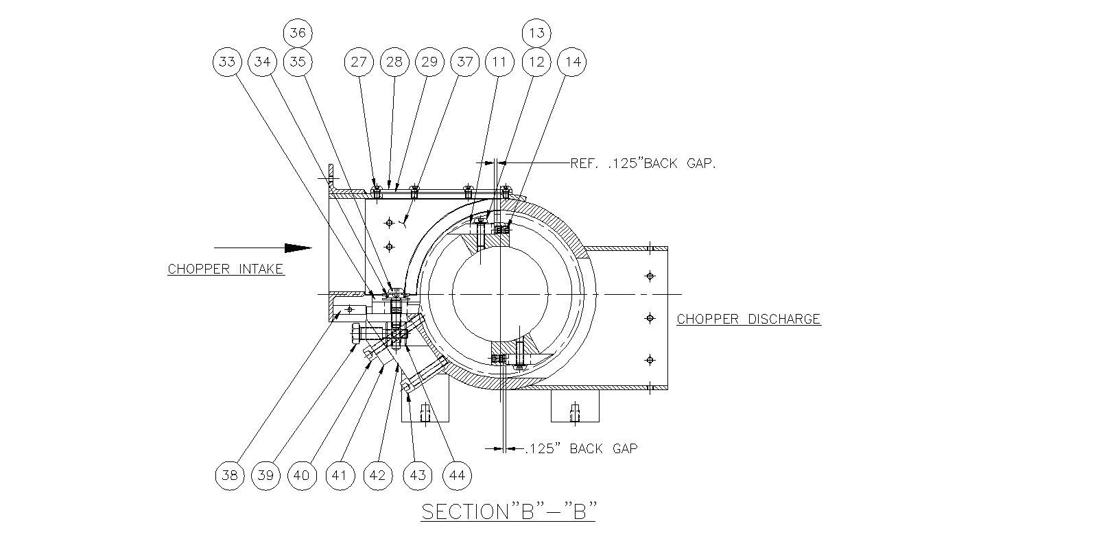
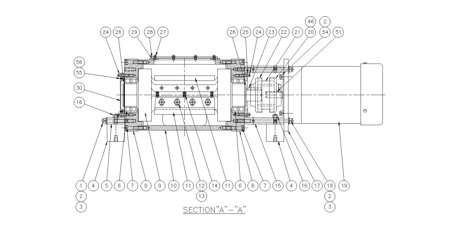
| Item No. | Description | Qty |
| 1 | 3/8-16 x 2 1/2" lg. SHCS | 2 |
| 2 | 3/8" lock washer | 10 |
| 3 | 3/8" plain washer | 6 |
| 4 | Foot Mount | 4 |
| 5 | Foot Plate | 1 |
| 6 | Ball Bearing | 4 |
| 7 | 5/16 - 18 x 1 3/4" long SHCS | 12 |
| 8 | Housing Cap | 2 |
| 9 | 2 Blade Roter | 1 |
| 10 | Chopper Body | 1 |
| 11 | Roter Knife | 2 |
| 12 | 5/16-24 x 1" long Torx Button Head Screw | 8 |
| 13 | Roter Knife Disc Spring | 8 |
| 14 | 5/16-24 x 5/16" long SSS | 12 |
| 15 | Motor Mounting Plate Stand Off | 1 |
| 16 | 3/8-16 Hex Nut | 4 |
| 17 | Motor Mounting Plate | 1 |
| 18 | 3/8-16 x 6" long SHCS | 4 |
| 19 | Motor 2HP | 1 |
| 20 | Flex Flange with 5/8" thru bore | 1 |
| 21 | Coupling Sleeve (insert) | 1 |
| 22 | Flex Flange with 1 3/8" thru bore | 1 |
| 23 | 5/16" square x 1.5" long key | 1 |
| 24 | 1/4-20 x 1" long SHCS | 8 |
| 25 | Brg. Cap Coupling Side | 1 |
| 26 | 65mm External Retaining Ring | 2 |
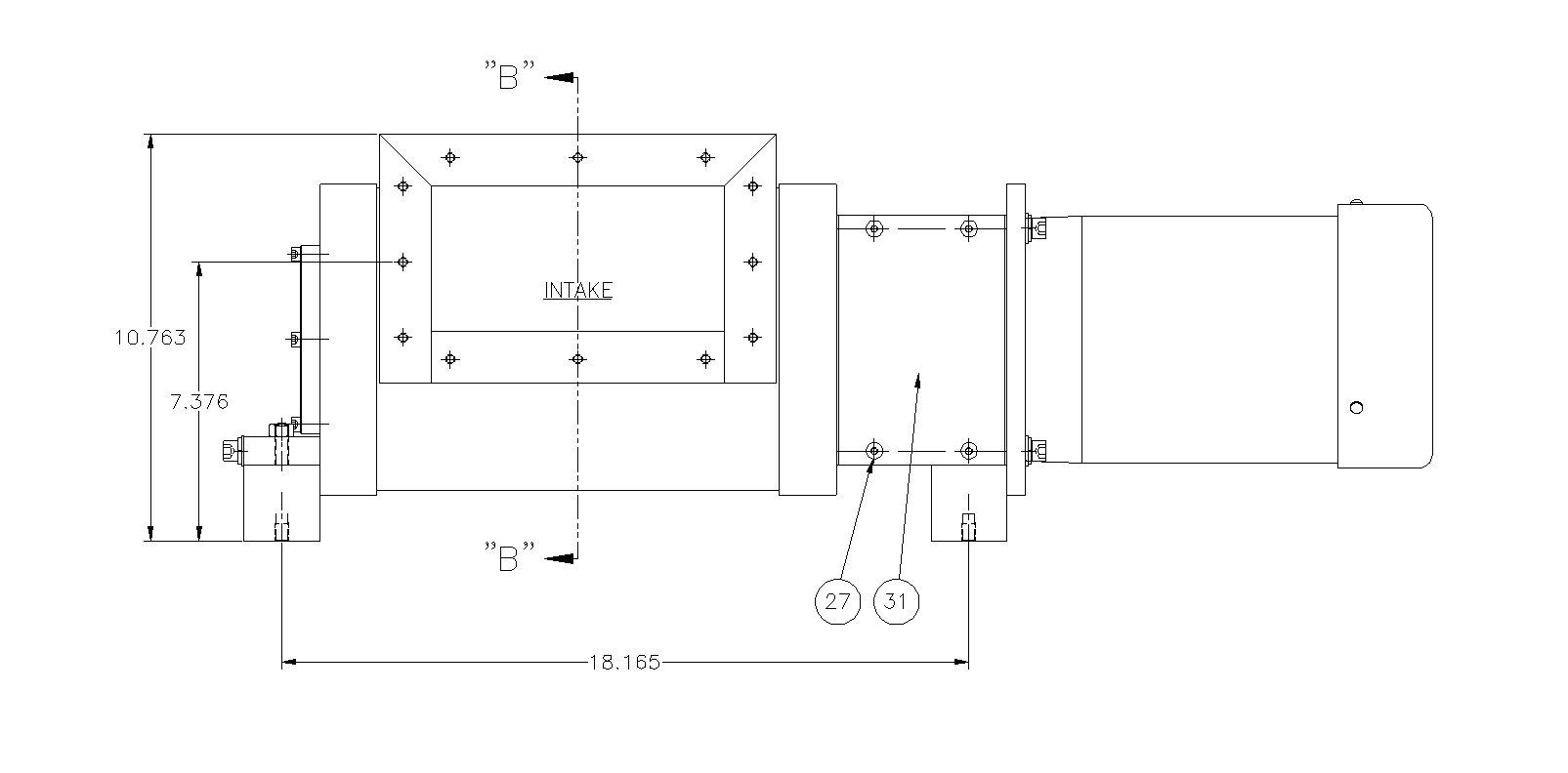
| 27 | 1/4-20 x 1/2" long BHCS | 20 |
| 28 | Intake Housing Top Cover | 1 |
| 29 | Intake Housing Top Cover Seal Gasket | 1 |
| 30 | Brg. Cap | 1 |
| 31 | Coupling Guard | 2 |
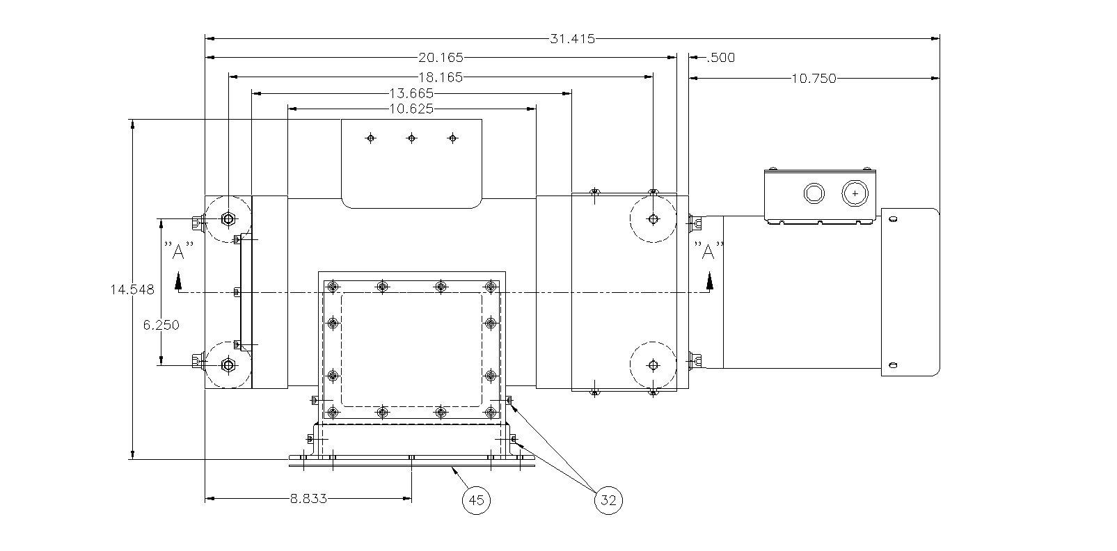
| 32 | 1/4-20 x 5/8" long SHCS | 6 |
| 33 | Carbide Bedknife | 1 |
| 34 | 3/8-24 x 1 1/4" long FHCS | 2 |
| 35 | 3/8-24 x 1 1/4" long BHCS | 3 |
| 36 | Bedknife Disc Spring | 3 |
| 37 | Intake Housing Filler Plate 1 per side | 1 |
| 38 | Intake Bedknife Filler Strip | 1 |
| 39 | Bedknife Adj. Bolt | 2 |
| 40 | 3/8-24 x 2 1/2" SHCS | 4 |
| 41 | Bedknife Black Plate | 1 |
| 42 | Bedknife Mounting Block | 1 |
| 43 | 3/8-24 x 1 3/4" long SHCS | 4 |
| 44 | Bedknife Adj. Cylinder | 2 |
| 45 | Intake Transition Seal Gasket | 1 |
| 46 | Coupling Assembly | 1 |
| 51 | 3/16" square x 1.5" long key | 1 |
| 54 | 3/8-16 x 1" long SHCS | 4 |
| 55 | #10-32 x 3/8" long SSS Flat Point | 4 |
| 56 | #10-32 x 1/4" long SSS Flat Point | 4 |
INTERNATIONAL CUSTOMERS


FOR THE LATEST NEWS & UPDATES