

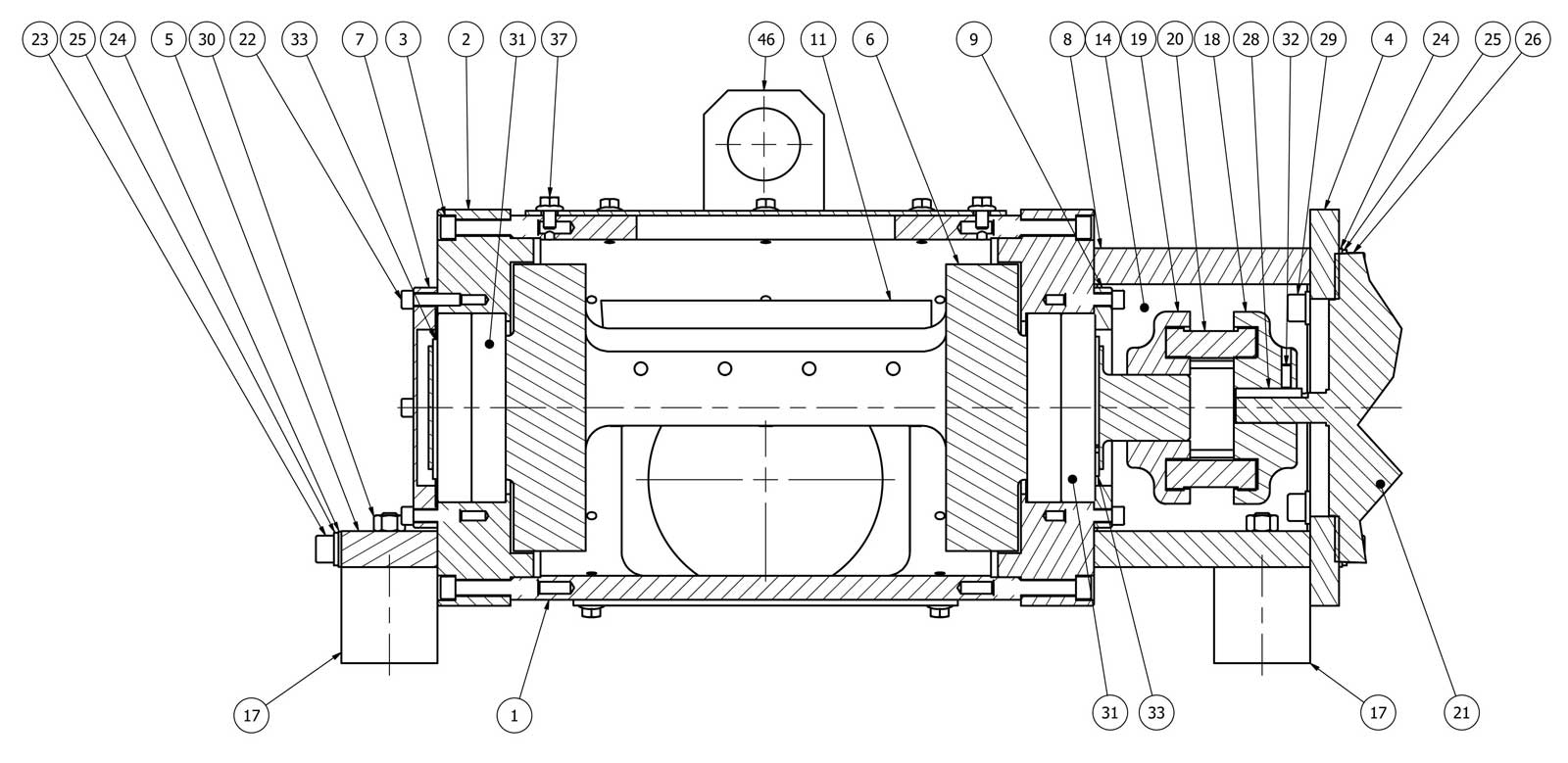
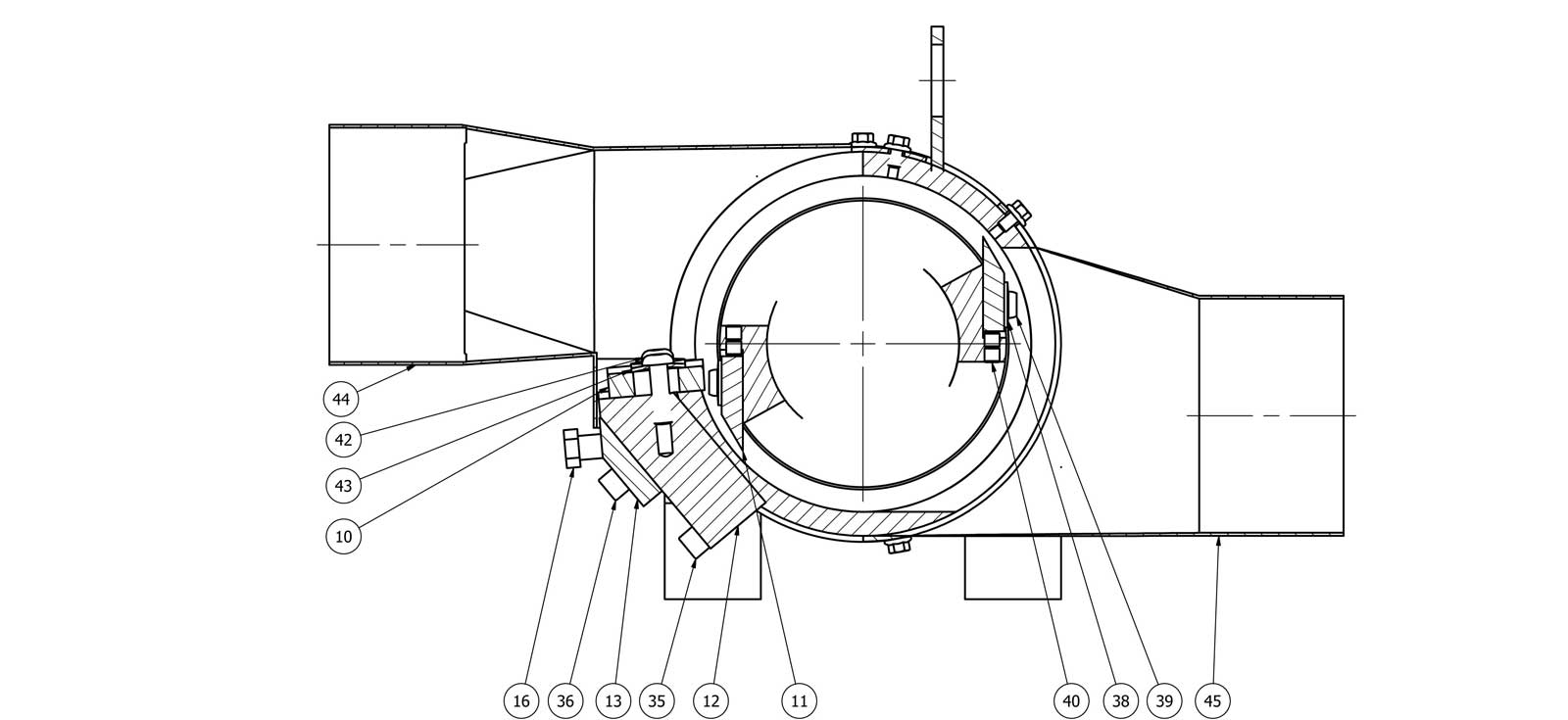
| ITEM | PART NO. | DESCRIPTION | QTY |
| 1 | 40511-98 | Chopper body | 1 |
| 2 | 40511-11A | Chopper housing cap | 2 |
| 3 | -H- | 5/16-18 x 1-3/4" LG SHCS | 12 |
| 4 | 40511-16A | Motor mounting plate | 1 |
| 5 | 40511-20 | Foot plate | 1 |
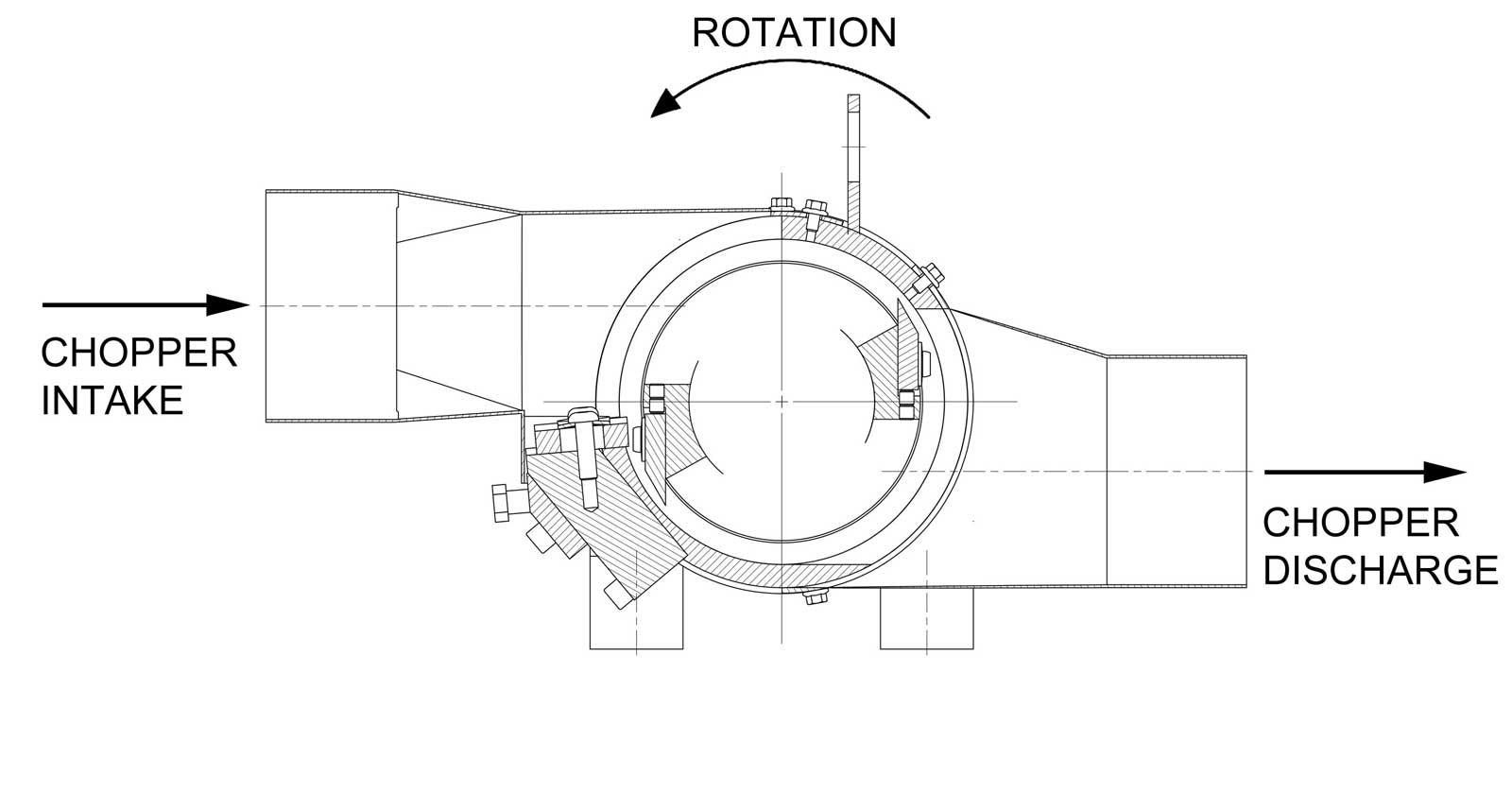
| 6 | 40511-09D | 2-Blade rotor welded assembly | 1 |
| 7 | 40511-19B | Bearing cap | 1 |
| 8 | 40511-17 | Motor mounting plate stand-off | 2 |
| 9 | 40511-18 | Bearing cap coupling side | 1 |
| 10 | 40511-12A | Carbide bedknife | 1 |
| 11 | 40511-13C | Rotor knife | 2 |
| 12 | 40511-14C | Bedknife mounting block | 1 |
| 13 | 40511-15D | Bedknife back plate | 1 |
| 14 | 40511-21A | Coupling guard | 2 |
| 15 | 40511-27B | Bed knife adjust cylinder | 2 |
| 16 | 40511-28B | Bed knife adjustment bolt | 2 |
| 17 | 40511-30 | Foot mount | 4 |
| 18 | 40511-31 | Flex flange with 5/8" diameter thru bore | 1 |
| 19 | 40511-32 | Flex flange with 1-3/8" diameter thru bore | 1 |
| 20 | 40511-33 | Coupling sleeve insert | 1 |
| 21 | 40511-35 | Motor 2HP | 1 |
| 22 | -H- | 1/4-20 x 1.00" LG SHCS | 8 |
| 23 | -H- | 3/8-16 x 2-1/2" LG SHCS | 2 |
| 24 | -H- | 3/8" Plain washer | 6 |
| 25 | -H- | 3/8" Lock washer | 10 |
| 26 | -H- | 3/8-16 x 6.00" LG SHCS | 4 |
| 27 | -H- | 5/16 x 5/16 x 1.50" LG Sq Key (Rotor shaft) | 1 |
| 28 | -H- | 3/16 x 3/16 x 1.37" LG Sq Key (Motor shaft) | 1 |
| 29 | -H- | 3/8-16 x 1.00" LG SHCS | 4 |
| 30 | -H- | 3/8-16 Hex nut | 4 |
| 31 | 40511-40 | Ball bearing | 4 |
| 32 | -H- | 10-32 x .50" LG SSS Flat point | 4 |
| 33 | -H- | 65 MM External retaining ring | 2 |
| 34 | -H- | 1/4-20 x 3/8" LG BHCS | 8 |
| 35 | -H- | 3/8-24 x 1.75" LG SHCS | 4 |
| 36 | -H- | 3/8-24 x 2-1/4" LG SHCS | 4 |
| 37 | -H- | 1/4-20 x 3/8" LG Hex flange head cap screw | 18 |
| 38 | 40511-45A | Rotor knife disc spring | 8 |
| 39 | -H- | 5/16 x 1.00" LG Torx button head cap screw | 8 |
| 40 | -H- | 5/16-24 x .31" LG SSS Flat point | 12 |
| 41 | -H- | 3/8-24 x 1.25" LG FHCS | 2 |
| 42 | -H- | 3/8-24 x 1-1/4" LG BHCS | 3 |
| 43 | 40511-44 | Bed knife disc spring | 3 |
| 44 | 40511-101 | 5" Flanged intake transition | 1 |
| 45 | 40511-102 | 5" Discharge flanged transition | 1 |
| 46 | 40511-78A | Lifting tab | 1 |
| 47 | -H- | 1/4-20 x 3/8" LG SSS Flat point (rotor coupling) | 2 |
INTERNATIONAL CUSTOMERS


FOR THE LATEST NEWS & UPDATES