
FOX TrimAway® Installation and Operating Instructions
|
Familiarize Yourself with the System Components |
| Check your shipment against the packing list, the original quote and the following drawings. Contact us immediately if there is any shortage. Contact us at sales@converteraccessory.com |
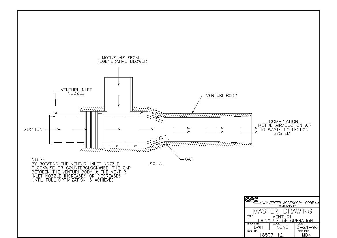
Operating Principle |
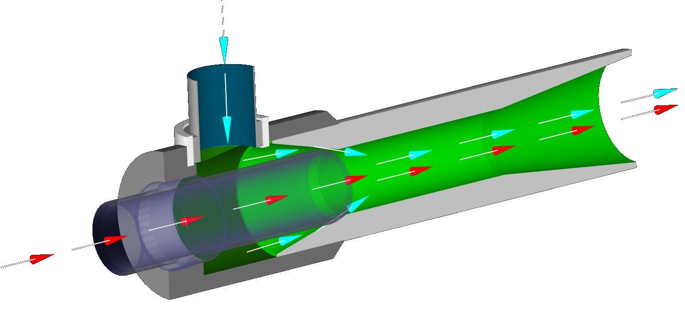
The FOX TrimAway® system utilizes the venturi principle combined with a powerful regenerative blower. The output of the blower is piped into the venturi, there the venturi creates suction at the intake point and pressure at the discharge point (see drawing number 18503-12 below). The trim or matrix is allowed to pass through the venturi and be discharged to the waste collection area without being chopped.
|
Wiring the Blower |
We recommend the blower be wired by a licensed electrician or an experienced plant mechanic. If the blower is 3-phase, an appropriately sized motor starter, fused not to exceed maximum blower amps (as indicated on blower) will be required. Install the blower inlet filter, using the filter mounting assembly as shown in the following system layout drawings before start-up. Following the diagram on the motor plate, wire for low or high voltage. Be sure the motor is turning in the proper direction (this can be determined by following the directional arrow or imprinted on the blower or by looking directly into the backside of the cooling fan and checking for clockwise rotation). If the rotation is backwards, shut off the power and reverse any two (except ground) wires. After connecting the venturi properly (see "Venturi Connections & Mounting in this document), measure the current/amps. DO NOT EXCEED THE MAXIMUM BLOWER AMPS. If the current/amps exceed the maximum blower amps, the venturi optimization must be decreased (See"Venturi Adjustment" in this document). Any blower failure caused by exceeding the maximum blower amps will VOID WARRANTIES. |
Venturi Connections and Mounting |
Motive Connection |
Connect the blower output adapter (barbed hose fitting) into the OUT port of the blower. Attach the proper length of motive hose (neoprene impregnated construction) between the blower and venturi motive connector (see following system layout drawings). Use hose clamps to clamp motive hose in place. Typically the motive distance is not critical. Avoid any elbows by using flexible neoprene hose for bends. Make sure there are no air leaks between blower and venturi. Check the suction at the venturi inlet and pressure from the discharge end. If you are getting no, or very little, suction/pressure, proceed to the Venturi Adjustment section of these operating instruction. |
Venturi Mounting |
 Click image to enlarge |
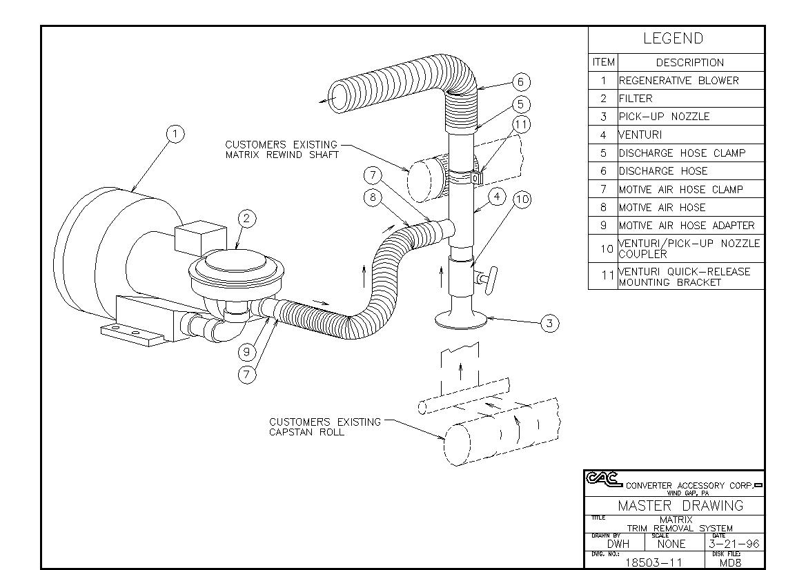
Matrix Removal System - The standard matrix removal system is supplied with a special venturi mounting bracket. It is designed to mount directly to the existing 3 inch diameter matrix rewind shaft. It will be necessary to lock the rewind shaft so it does not rotate. The venturi should be mounted in the special venturi clamp and the matrix should follow its standard threading pattern (see drawing number 18503-11 below)
|
Intake Connection |
|
Two Pick Up System - Connect an intake hose length on the venturi inlet and the center leg of the wye connection. Connect two legs of intake hose to lead from pick up points to the wye. Try to keep both legs equal in length so the wye is located in the center. Attach the trim pick up nozzles to the intake hose legs with hose clamps (see drawing number 18503-09 below)
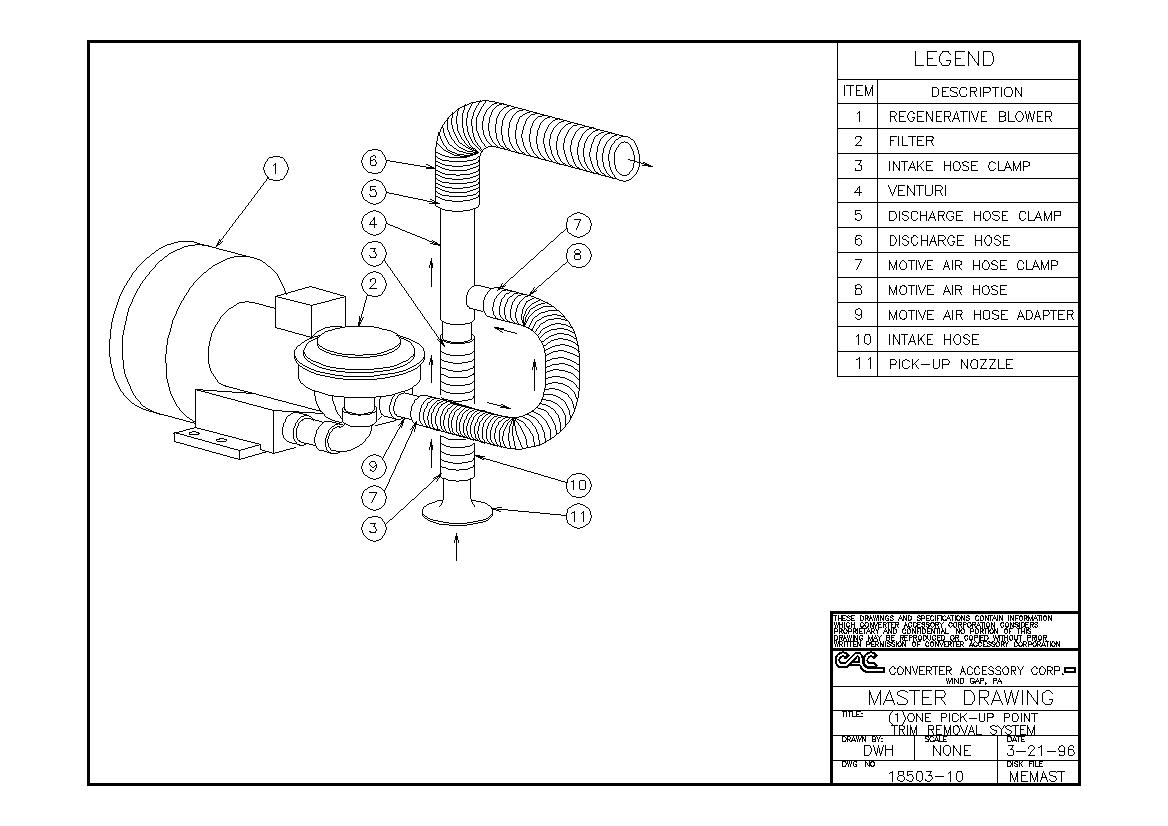
One Pick Up System - Connect an intake hose length on the venturi inlet. Attach the trim pick up nozzle to the intake hose (see drawing number 18503-10 below).
Matrix Removal System - Using the Venturi/Pick up nozzle coupler, connect the pick up nozzle (see drawing number 18503-11 below).
|
Discharge Connection |
Slip the discharge hose over the discharge end of the venturi and secure it with a hose clamp. Route the discharge hose to your collection point, use flexible steel hose (supplied) for all bends. Use rigid pipe for long, straight discharge lengths. |
Collection Containers |
Your collection container should allow for the free discharge of air and material. If it does not allow adequate air ventilation or is designed so the material can build up to the discharge line, back pressure will affect the performance of the system. Please contact us at sales@converteraccessory.com if you have any questions on this. |
Venturi Adjustment |
The venturi inlet nozzle is threaded into the venturi body. After loosening the set screw(s) located around the venturi body, the inlet nozzle should easily rotate to open or close the venturi gap (click here to see drawing number 18503-12). To Optimize the Venturi - Rotate the inlet nozzle counter clockwise so most of the threads are exposed. Slowly rotate the inlet nozzle clockwise, you will feel the suction increase, as you continue to rotate the nozzle clockwise you will feel the suction start to decrease, back the nozzle out to the point of greatest suction. To Decrease Venturi Optimization- Rotate the inlet nozzle counter clockwise until desire suction / pressure is acquired. DO NOT DECREASE THE VENTURI OPTIMIZATION BY ROTATING THE VENTURI INLET NOZZLE CLOCKWISE (CLOSING THE GAP) AS THIS WILL PUT UNNECESSARY STRAIN ON THE BLOWER MOTOR AND MAY CAUSE DAMAGE BE EXTREMELY CAREFUL, THE VENTURI THREADS ARE ALUMINUM AND VERY EASY TO CROSS. IF THE VENTURI THREADS GET CROSSED DO NOT FORCE THE VENTURI INLET NOZZLE TO ROTATE, CONTACT THE FACTORY IMMEDIATELY. |
Installation and Operating Tips |
|