Do you use cantilevered unwind and rewind shafts in your operation?The biggest advantage to using cantilevered shafts is the ability to make speedy roll changes. One way to speed up roll changes is to supply air shafts with pneumatic pressure through rotary union connection. When you use rotary union air supply to your air shafts, inflating and deflating occurs by simply flipping a pneumatic toggle valve. This is much faster than inflating air shafts with an inflating gun.
To make roll changes extremely efficient, consider air shafts with built-in toggle valves (installed in the end of the shaft opposite the rotary union). Air shafts with built in toggle valves allow operators to load and unload rolls in the least amount of time because the toggle valve inflate / deflate operation is located at the center of the roll change itself.
To learn more, click here!
|
|
|
| Tip No. 1
|
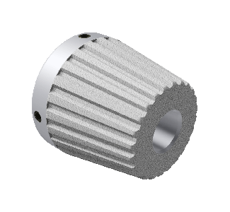
How do you hold your cores?Do you use core cones or something similar, like "end plugs" or "dummy chucks" to hold your cores on your unwind or rewind equipment? If you do, find out how they mount on your thru shaft. Oftentimes this type of core holding device has set screws that directly contact the thru shaft. If that is the case in your operation, you may want to invest in units with bushing type locking.
We manufacture and sell aluminum core cones. Our standard units include set screws that directly contact the thru shaft. Over time, these set screws can mar the thru shaft, making it impossible to remove the core cones. We offer split bushing locking as an option, for a few dollars more. This option ensures the set screws will not come in contact with the thru shaft, thus saving your machine operators tons of time and lots of aggravation. This small investment will prove very fast return in time saved.
|
|
|
| Tip No. 2
|
Core adapters are an inexpensive, time saving answer to a perplexing problemDo you have a customer who wants material on a larger core than you currently process? Do you have a supplier that supplies rolls of material on larger cores than you normally unwind?
Core adapters may be the answer to allow you to occasionally run varying core sizes. Most common core sizes are 3" and 6". Often times you may normally run 3" cores but occasionally may have to run 6". Core adapters come in various designs, each with advantages and disadvantages and costs associated with each type.
Core adapters slide on top of your existing air shaft and allow you to lock larger cores on to the air shaft "base". Some adapters utilize the expansion of the air shaft to activate the locking mechanism of the adapter. These types of core adapters are less expensive, but provide much less torque than an independently activated pneumatic adapter.
Some core adapters lock with built-in bushings to your existing air shaft. They inflate independently of the air shaft to which they are mounted. Their initial cost is higher but they provide very even, high core locking torque. Because they stay locked in place on your air shaft, regardless of whether your air shaft is inflated or not, they are the easiest and fastest to operate, providing very fast return on the initial investment.
|
|
|
| Tip No. 3
|
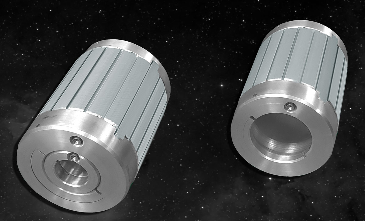
Core cones can be an inexpensive answer to a very expensive problemDo you ever have to unwind rolls that have crushed cores? Crushed cores can be caused by many factors. However, finding reasons crushed cores occur and correcting them won't help you run the rolls with crushed cores you have to run now. And correcting crushed core problems is an issue to be discussed in another article.
Air shafts and air chucks won't fit inside crushed cores so your choice is to try to fix your cores with expensive core repair devices (that may or may not correct the problem) or to simply use inexpensive core cones to hold your roll of material. Core cones are cone shaped devices that are inserted into each end of the core. Their minor diameter is usually small enough to fit inside even the most distorted crushed core. These inexpensive, easy to use core holders will allow you to run rolls with crushed cores.
Another tip: buy the core cones with split bushing locking, instead of having the set screws contact your thru shaft directly. This will save your thru shaft from being damaged and will save your machine operators tons of headaches when loading and unloading rolls.
|
Click here for more information on our Core Cones |
|
| Tip No. 4
|

Mechanical chucks may be the answer for your core support requirements
Mechanical chucks have some advantages over their pneumatic counterparts. Here are some advantages to using mechanical chucks instead of air chucks:
- Initial lower cost. Mechanical chucks are often simpler than pneumatic chucks, so they are usually less expensive.
- Here's an obvious one - you don't have to inflate them! So, you don't have to run pneumatic piping and inflation devices to use them.
- Most designs are "torque sensitive", which means the more torque you apply to them, the harder they grab. Air shafts and chucks have a set amount of torque they can deliver. If your application demands more torque, air shafts and chucks will slip.
- Mechanical chucks are light weight.
- Most designs are easy to use and core locking may be "automatic" with core rotation.
- Large bore to core size allows for lots of beam strength with large thru shafts and journals.
- Most mechanical chucks can be used as core adapters where larger than normal cores are sometimes needed.
Mechanical chucks have their place for effectively holding a roll in unwind and rewind applications. Often times they are the best choice.
|
Click here for more information on our Mechancial Chucks |
|
| Tip No. 5
|
Do you have crushed cores or lateral wrinkling of your web near the roll core? Consider that your rewind roll is basically similar to a very large clock spring. If you rewind your rolls with constant tension, in-wound pressure builds with every layer wrapped onto the rewind. This pressure may be so great in towards the core that the inner layers of the roll may buckle on themselves, causing lateral wrinkles and defects across the web. This pressure may be so great that you may even crush your cores.
If you don't see these defects in your rewound rolls, great! Don't change any system that works. However, if you do see defects in your rolls towards the core or crushed cores, taper tension may solve your problem.
Automatic tension controls with built in taper tension capability allow you to decrease tension at a controlled rate as the rewind roll builds. Decreasing tension as the roll is rewound will decrease the pressure in the "clock spring". Proper taper tension control will eliminate problems with the inner layers of your rewound rolls by decreasing the pressure build up. |
|
|
| Tip No. 6
|
As the printing and converting process becomes more and more digital, does the role of cores, shafts and chucks change?In all web processes, continuous roll quality is an important part of web stability, production quality and end product quality.
Shafts and cores are similar to a building's foundation. If the foundation is poorly constructed, not level or out of square, the entire building suffers. As the building goes up the impact of the defects increase. The same is true with rolls. If the core or shaft is of poor quality the roll may be defective.
As printing and converting become more digital, the role of air shafts becomes more important. The precision tuning of processes made possible by digital controls allows printers and converters to run at higher speeds and deliver higher quality finished products. Higher speeds place greater stress on the roll and on the shaft's ability to hold securely to the core.
For more info, click here
|
Click here for more info on our Core Holders |
|
| Tip No. 7
|
Adding a Nip Roll AssemblyNip roll assemblies include 2 rolls that are "loaded" together so that there is pressure applied to whatever is fed between the two rolls. Nip rolls can be used to assist in laminating operations where two or more layers of webs are to be bonded to one another. Nip rolls are also used to "divorce" tension zones. Here are some things to consider when choosing a nip roll design for whatever application your may have for them:
- You may have to drive the nip roll assembly, so get a drive supplier involved in the conversation to discuss line speed and tension issues.
- Loading. There are several ways to load nip rolls, spring loading, air loading and mechanical loading. Keep in mind, there may be safety issues when considering that type of loading.
- Rubber covering one, both or none of the rollers in the nip roll assembly.
- If you are going to rubber cover any of the rollers in the nip roll assembly, consider what type, thickness and hardness of the rubber is desired.
- Roll finishes are often important.
- Deflection calculations should be completed and the nip roll assembly should be designed to limit the amount of roller deflection.
Many other considerations may arise for your specific application. Be sure all variables are accounted for in the nip design to provide the best possible performance for your application. |
|
|
| Tip No. 8
|
Nip Rolls Should Be Used for Joining Layers of WebsNip rolls should be utilized in most laminating and inter-leaf applications. Using nip rolls will benefit most multi-layer web joining operations by:
- The nipping action will remove air and air bubbles.
- Nip rolls provide web support through the process. This keeps the web properly positioned by providing more stability to the process itself.
- Properly supporting the webs through the nipping process will help to eliminate the potential for the web to wrinkle.
Bottom line, most applications where two or more layers of web are being joined should use nip rolls at the joining process.
For more informatin or to watch a video on CAC nip roll assemblies, click here|
|
|
| Tip No. 9
|
Where to place an Idler Roll when guiding an Unwind and Rewind Stand?When using an automatic web guide system on an unwind stand, where the unwind moves laterally, side to side, a lead-out idler roll MUST be included that moves with the unwind stand's motion. If this idler roll is not present in the control scheme, chances are the unwind will oscillate or "hunt" continuously, decreasing the accuracy of the guide and increasing your maintenance department's headaches. The web guide control's web detector (edge, line or centerline resolver) must be mounted AFTER the moving lead-out idler roller.
When using an automatic web guide system on a rewind stand, where the rewind moves laterally, side to side, a lead-in idler roll MUST be included that is stationary. This roller must not move with the rewind stand. The web guide control's web detector must be mounted prior to the stationary idler. In other words, the stationary idler roller must be mounted between the web detector and the rewind stand. The web guide system will continually oscillate if you do not maintain this control scheme. One more thing about guiding a rewind stand in this fashion; keep in mind, this is not a web guide system in the true sense of the phrase. This is really a chasing operation. In other words, you are not positioning the web where is it supposed to be in the process; instead, you are moving the rewind to wherever the web goes. You are in essence chasing the rewind to the web.
|
|
|
| Tip No. 10
|

 Please wait