
 Please wait


How do open loop tension controls work?
First, a word about the term drive.
In many of the descriptions throughout this presentation I refer to the term “drive”. I am using this term as a purely generic term to describe a mechanical device that delivers torque to a roll of material or driven roll(s) in a converting machine. This device could be a motor, brake or clutch. This presentation is not meant to detail drive mechanisms; instead its intent is to describe the fundamental mechanics of tension control systems.
Manual tension control.
The simplest and least expensive method of tension control is manual. They can be as simple as a potentiometer adjusting the torque output of a drive or magnetic particle brake or clutch or an air regulator adjusting the air pressure and therefore torque output of an air brake or clutch. This control method can be used in all three tension zones. Obviously, it is the least accurate of all types of tension controls because it relies completely on operator “feel” to set the proper tension. There is no feedback from the machine to verify any actual process tension levels. Often times they will have some sort of “meter” on the front of the control to display output as a reference point.
Unwind and rewind tension zones are the most difficult to control manually because of constantly changing diameters and therefore need to be constantly adjusted.

Diameter measurement control.
There are several types of diameter measurement controls. Each type has its own method of sensing the unwind and rewind roll diameter. These controls are extremely useful for controlling the tension off an unwind and onto a rewind. However, because they control tension by proportionally decreasing (unwind) or increasing (rewind) torque relative to roll diameter change, they do not work for internal tension zones. These types of tension controls are used strictly at the unwind and rewind tension zones. These controls can be supplied with taper tension for rewind zone applications.
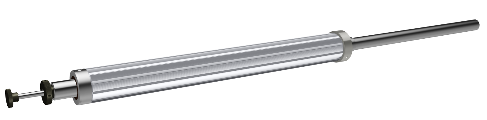
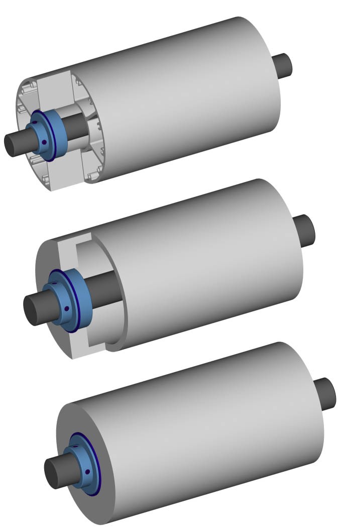
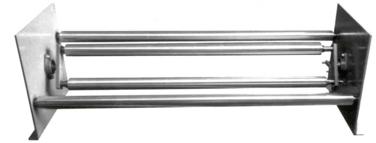
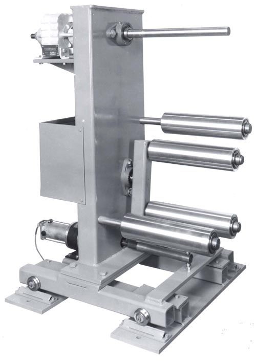
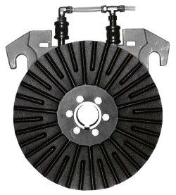
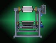
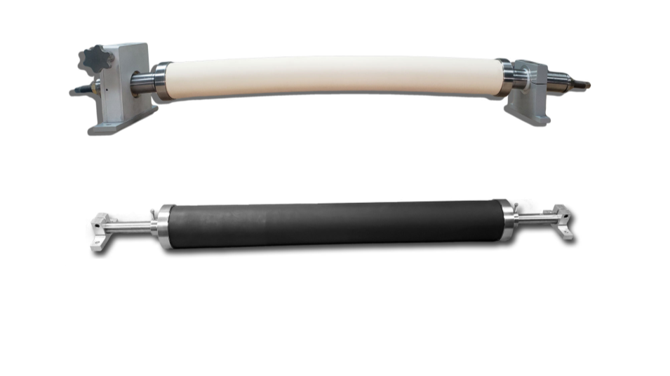
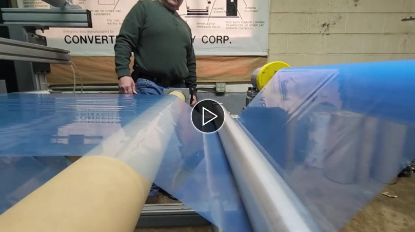
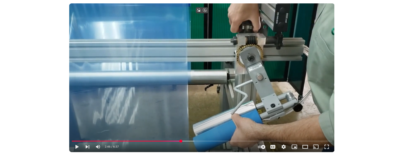
Diameter measurement control – follower arm.
Follower arm or lay-on roll type control is the oldest technology for diameter measurement. This type of control has a wheel or roll, which lays on the unwind or rewind roll outer diameter. The wheel or roll is mounted to a pivoting arm. The pivoting arm is spring or air loaded with a sensing device mounted to the pivot point. The sensing device is usually a potentiometer, but proximity sensors and hall-effect sensors are also common. This sensing device feeds back to the tension control and an output is generated to the drive to control torque proportional to roll build.

Follower arm tension control advantages:
- This type of tension control is very simple.
- Good replacement for operator controlled manual control.
- Inexpensive.
- Easy to install.
Follower arm tension control disadvantages:
- Normally, this control does not have compensation for out of round rolls. Out of round rolls could cause this control to oscillate.
- The lay-on roll or wheel gets in the way of changing rolls.
- Major mechanical modifications are necessary to increase unwind or rewind roll capacity.
- There are a lot of mechanical parts, which will require maintenance.
- This is an open loop tension control. It does not control tension by measuring tension in the web. It controls tension by measuring roll diameter. It assumes all of the conditions effecting web tension are correct.
- This type of tension control can only control unwind and rewind zones. It cannot control internal zones.
- Material must be contacted, which could harm some sensitive materials.
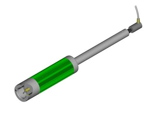
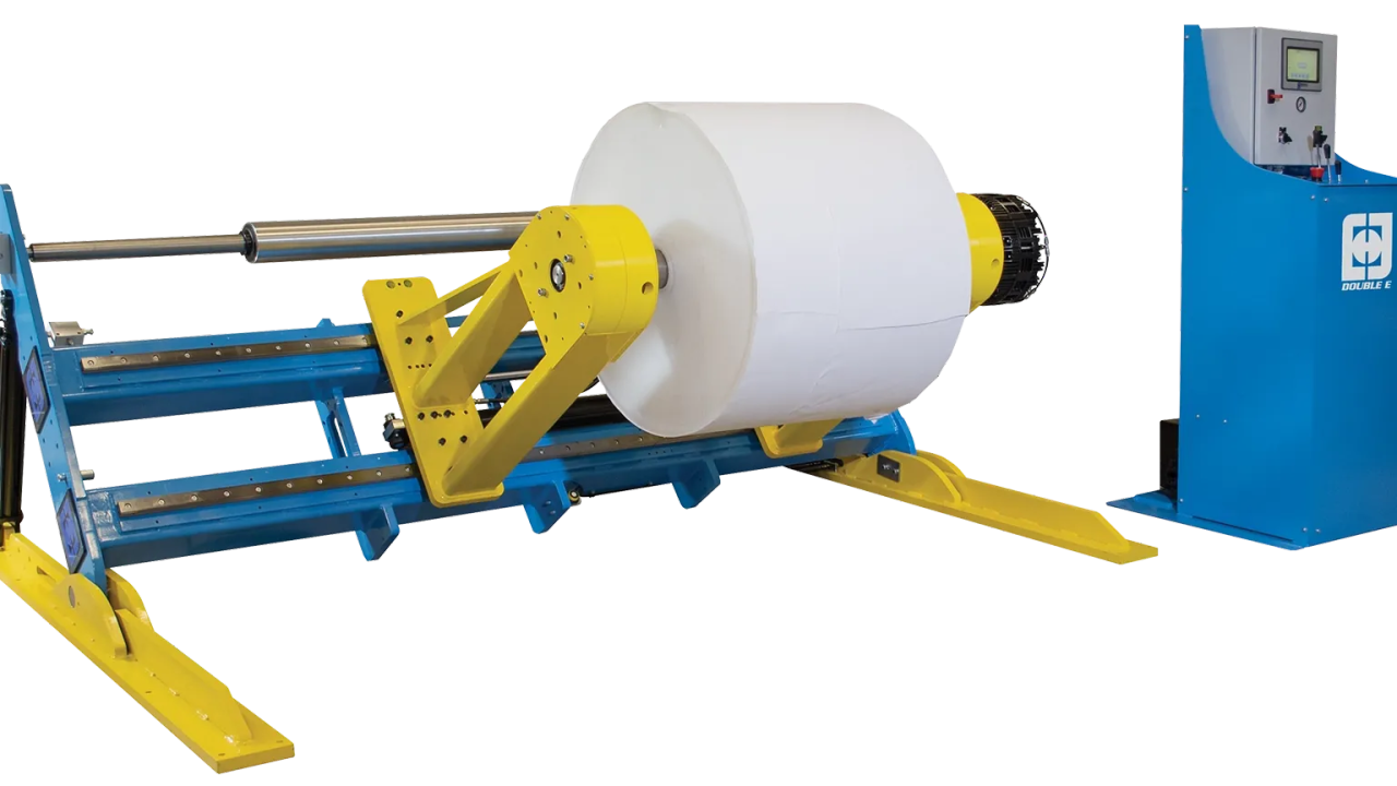
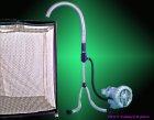
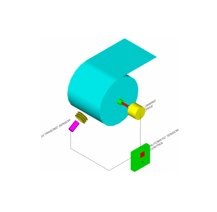
Diameter measurement control – ultrasound:
Many advantages over the follower arm type tension control make the ultrasound tension control a more popular choice today. The ultrasonic sensor emits a signal that travels to the rolls surface, bounces off and returns to the sensor. The control logic measures the time it takes for the signal to return to the sensor and in that way measures distance. Since the control measures distance, it will give a linear output relative to the radius of the roll to a drive device. As we discussed earlier, the equation torque = tension x radius is linear, so if the ultrasound tension control gives a linear output relative to radius it will control drive torque through an unwind or rewind roll built to supply constant tension.

Ultrasound tension control advantages:
- This type of tension control is very simple.
- Excellent replacement for operator controlled manual control.
- Relatively inexpensive.
- Extremely easy to install.
- Gives a true linear output relative to roll diameter.
- Models of this control are available with compensation for out of round rolls to eliminate control oscilation.
- Ultrasonic sensor can be “tucked” away, out of machine operators way. It can be mounted anywhere around the roll circumference, as long as it get a clear view of roll radius.
- Modifications to increase unwind or rewind roll capacity is easy. All that is needed is to move the transducer and recalibration.
- No mechanical parts to wear out.
- Models are available with limit alarms. Such as low or empty roll.
- No material contact for sensitive materials.
Ultrasound tension control disadvantages:
- This is an open loop tension control. It does not control tension by measuring tension in the web. It controls tension by measuring roll diameter. It assumes all of the conditions effecting web tension are correct.
- This type of tension control can only control unwind and rewind zones. It cannot control internal zones.
- Any object put between the roll outer diameter and the transducer affects it.
- Electronic calibration is necessary with initial set up.
- Some types of material, such as nonwovens, may absorb the ultrasonic signal. If the signal does not return to the sensor, it will not operate.
- The perpendicular positioning of the sensor relative to rolls centerline is somewhat critical. If the sensor is “knocked” out of position, it may not operate properly.
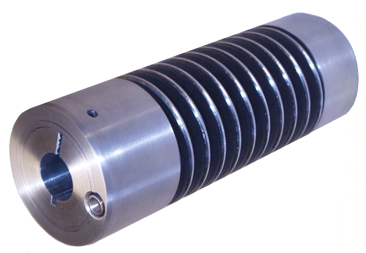
Diameter measurement control – diameter calculator
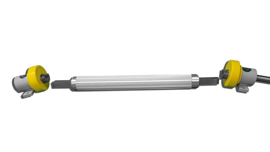
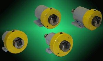
The last type of diameter measurement control we will discuss is the diameter calculator. This type of control uses sensors at the unwind or rewind shaft and an idler or driven roll. Both sensors detect RPM. They can be encoders or tachometer generators.
Machine speed is constant and known. Unwind and rewind roll speeds both vary relative to roll diameter. By comparing the constant known speed to the varying unwind or rewind roll speed, diameter can be calculated.

Diameter calculator tension control advantages:
- Excellent replacement for operator controlled manual control.
- Relatively inexpensive.